Rigging the SO-ARM 100 Robot: A Control Rig Journey

Complete workflow from CAD files to animated physics using Unreal Engine 5 Control Rig

My Journey with Control Rig

Over the past months, I've had the privilege of working alongside Epic Games' exceptional team, talented instructors, and an amazing technical artist to master one of Unreal Engine's most powerful features: Control Rig. What started as a technical challenge—rigging the SO-ARM 100 educational robot entirely within Unreal—became a transformative learning experience that fundamentally changed how I approach digital content creation.

Prerequisites

  • Unreal Engine 5.5+ (with Control Rig enabled)
  • FreeCAD (Download Free) - Open source CAD software
  • SO-ARM 100 STEP files - Original engineering files from the robot manufacturer
  • Basic understanding of 3D modeling concepts
  • Download the source files collection of 3D models converted and a uasset rigged robot.

Phase 1: Converting CAD Models to Unreal-Compatible Format

Step 1: Download the Original STEP Files

STEP files (.step or .stp) are the industry standard for CAD data exchange. Engineers use these files for manufacturing, rapid prototyping, and robotics applications. They contain precise geometric and assembly information that we'll leverage for our rig. You can download the open source original files from TheRobotStudio Github.

Why STEP files?

  • Parametric data preservation
  • Industry-standard format across all CAD platforms
  • Contains accurate assembly hierarchies
  • Maintains precise measurements critical for robotic applications
STEP files overview

Step 2: Convert STEP to glTF Using FreeCAD

Download FreeCAD: https://www.freecad.org/downloads.php

Conversion Process:

  1. Launch FreeCAD and open your STEP file:
    • File > Open → Select your .step file
    • FreeCAD will import the complete assembly
  2. Verify the import:
    • Check that all parts are visible in the 3D viewport
    • Confirm the assembly hierarchy in the Model tree
    • Note any parts that may need repositioning
  3. Export as glTF 2.0:
    • File > Export → Choose "glTF 2.0 (*.gltf *.glb)"
    • Select .gltf format (not .glb) for easier debugging
    • Name it appropriately (e.g., SO-ARM-100.gltf)

Why glTF?

  • Native Unreal Engine import support
  • Preserves hierarchies and transforms
  • Open standard with excellent tool support
  • Maintains material assignments
FreeCAD conversion step 1
FreeCAD conversion step 2

Phase 2: Preparing the Mesh to work in Unreal Engine

Step 3: Import and Transform Correction

Import the glTF into Unreal:

  • Drag and drop the .gltf file into your Content Browser
  • Unreal will create Static Mesh assets for each part, by default
  • You can drag all of the meshes selected into the scene and Combine them with modeling tools
  • Set option "combine mesh" in gLTF import settings to have it come in as one mesh
  • It's nice to have both imported - a version of the robot separated and combined - for rigging, bone placement, and weight painting

Fix Transform Offsets:

  • STEP files often have arbitrary pivot points and rotations
  • Open each Static Mesh in the Static Mesh Editor
  • Use Modeling Mode tools to correct positioning:
    • Select the mesh
    • Use the Transform tool to zero out offsets
    • Apply transforms: Right-click mesh → Bake Transform

Position the Arm for Rigging then combine:

  • Arrange the arm from a contracted state to a relaxed/extended state
  • This makes bone placement more intuitive
  • Keep parts slightly separated for easier weight painting later

Pro Tip: I found it helpful to separate the meshes initially rather than combining them immediately. This separation made weight painting much more manageable, as I could work on each servo and arm segment independently.

Unreal mesh import
Transform correction
Mesh positioning

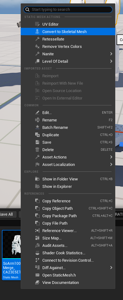
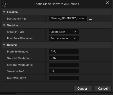
Step 4: Convert to Skeletal Mesh

  • Select all your prepared Static Meshes
  • Right-click → Select Convert to Skeletal Mesh
  • Unreal will create a new Skeletal Mesh asset
  • This creates a basic skeleton structure we'll refine

Phase 3: Skeleton Creation and Weight Painting

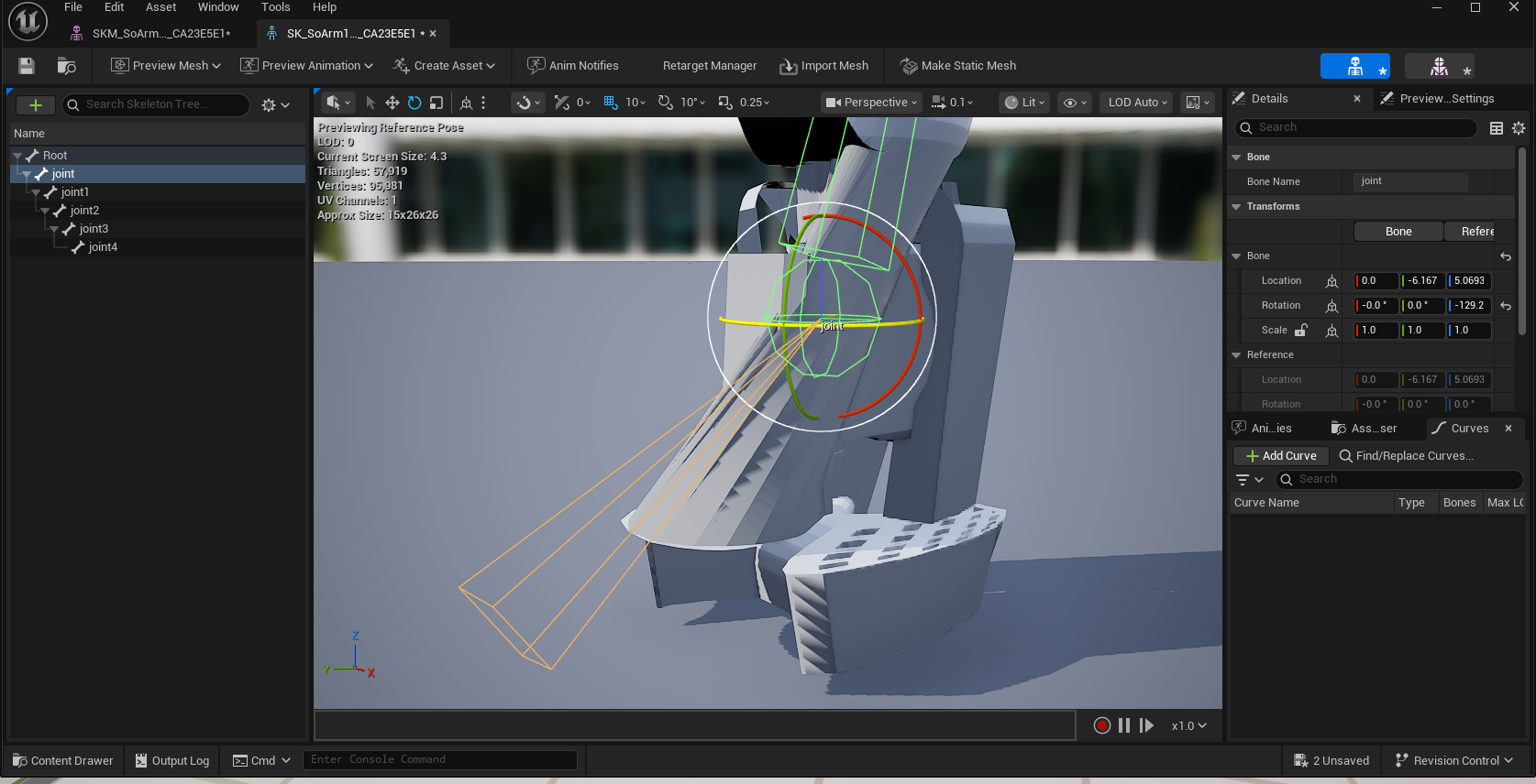
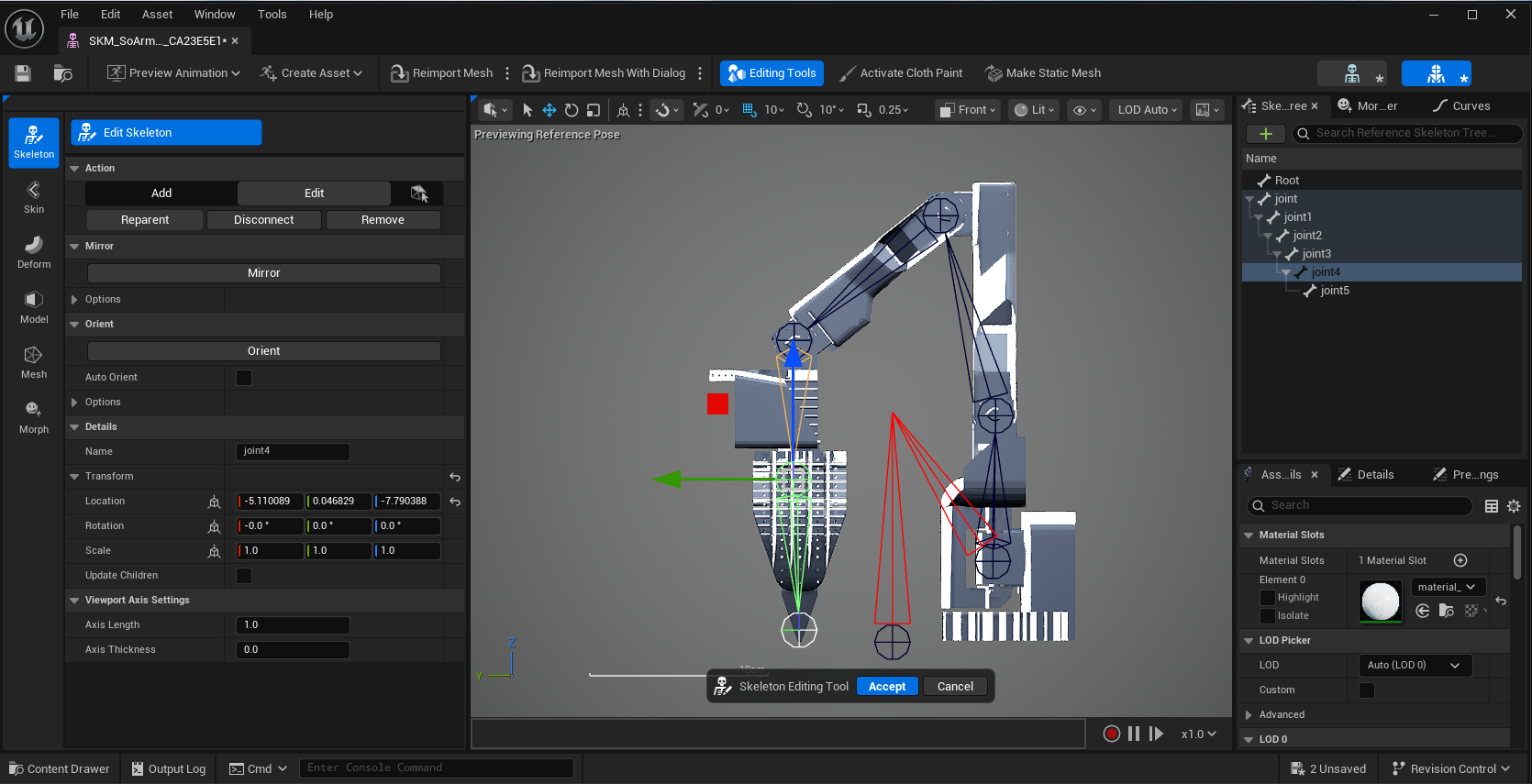
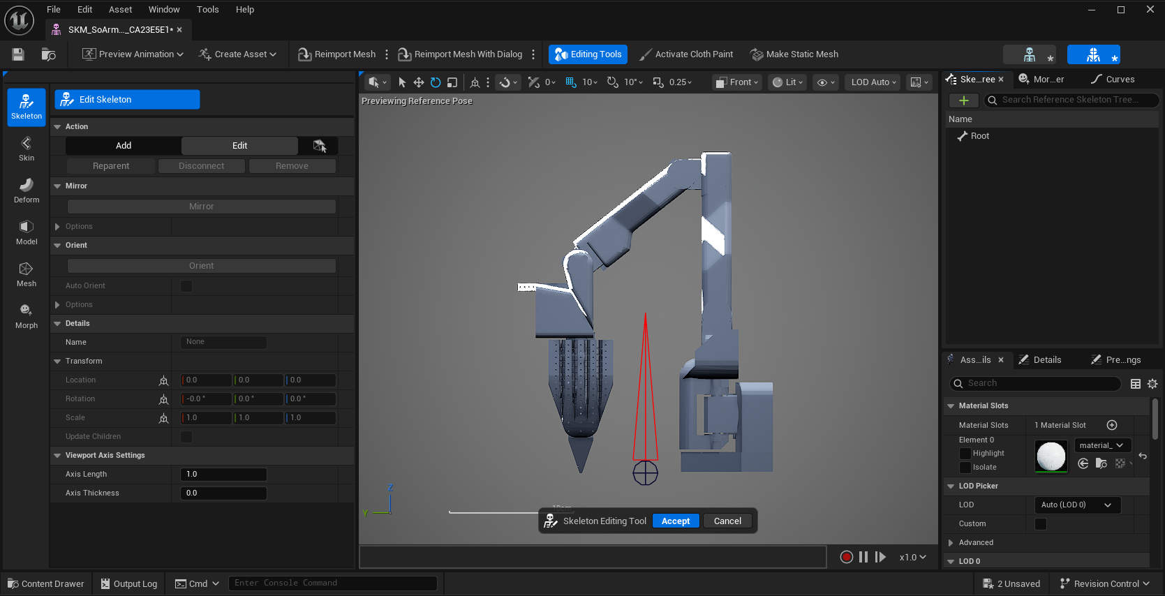
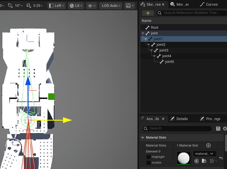
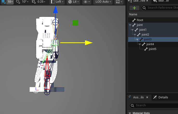
Step 5: Manual Bone Placement

This is where precision matters. The SO-ARM 100 has servo motors at each joint—these are our rotation points.

My Strategy:

  • Lock the viewport to Left/Side orthographic view for precision
  • Use the "Place Bones Into Mesh" tool from the Skeleton Editor
  • Place bones only at servo motor locations where actual rotation occurs

Bone Naming Convention:

  • Bones imported as: joint1, joint2, joint3, etc.
  • These maintain the correct parent-child hierarchy automatically
  • Each bone represents a degree of freedom in the robot

Why this approach works:

  • Matches the physical robot's actual articulation points
  • Simplifies the rig (only necessary joints)
  • Makes animation intuitive (each bone = one motor)
Bone placement

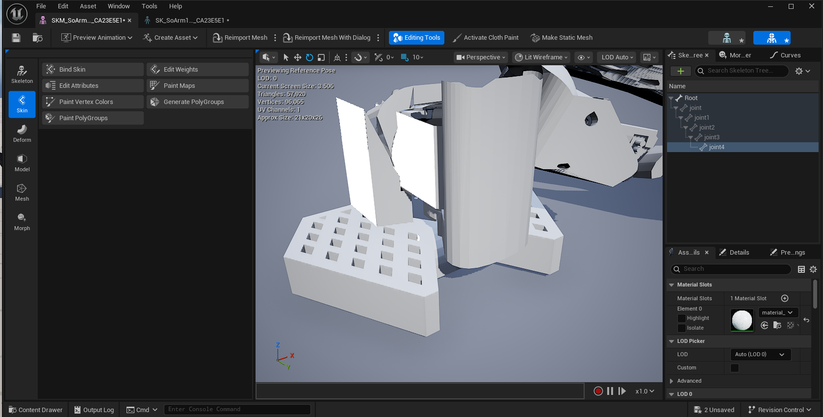
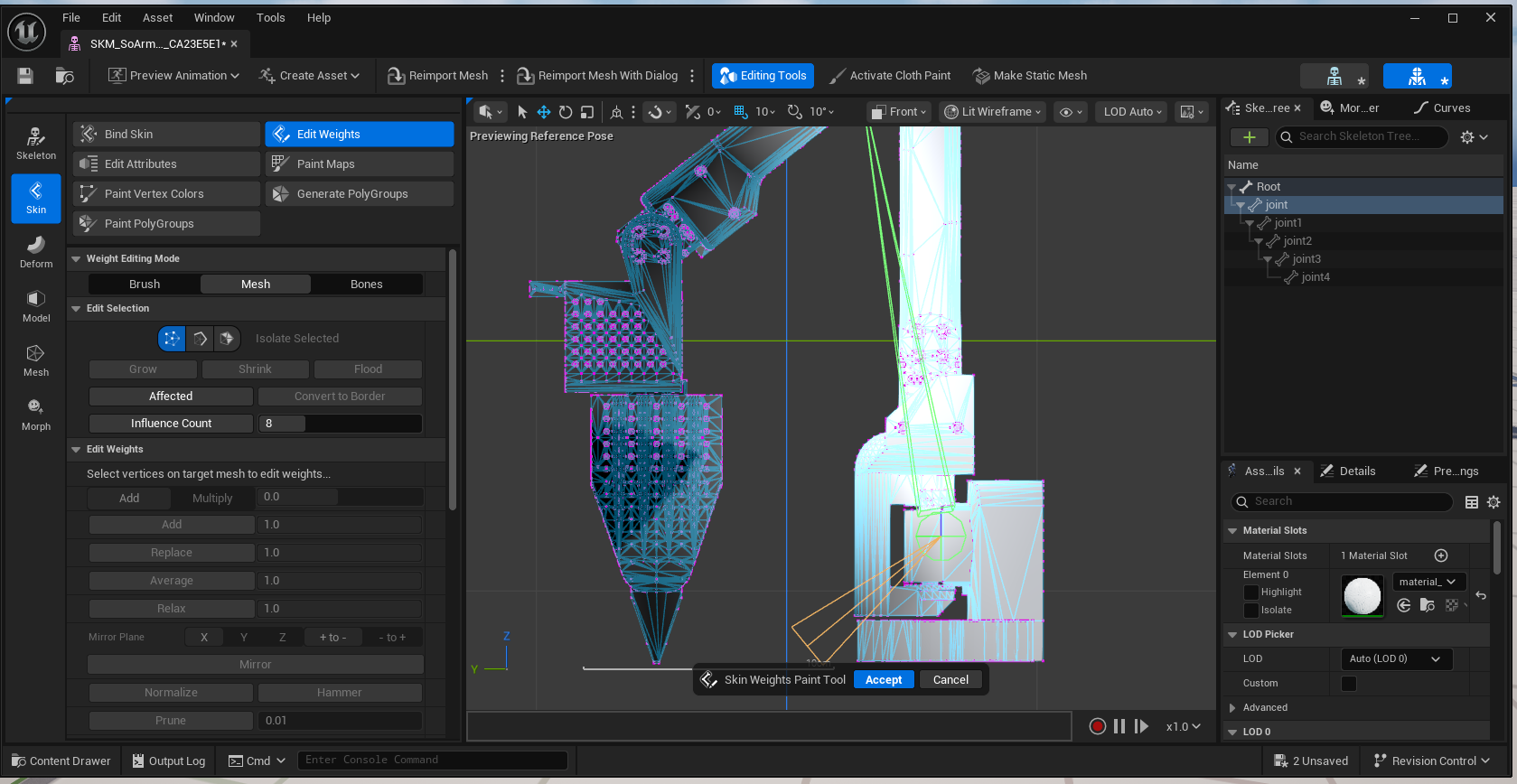
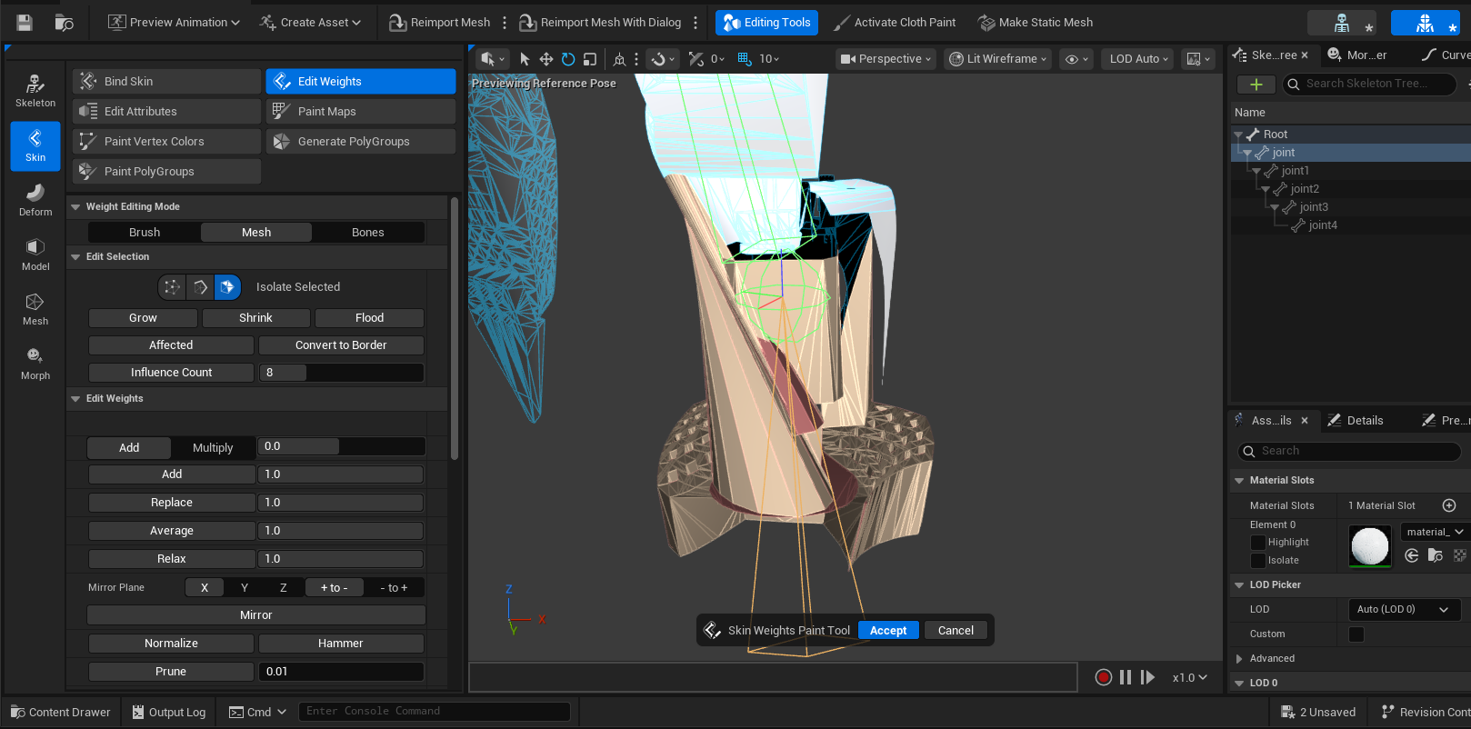
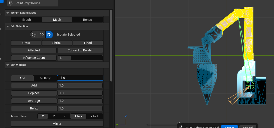
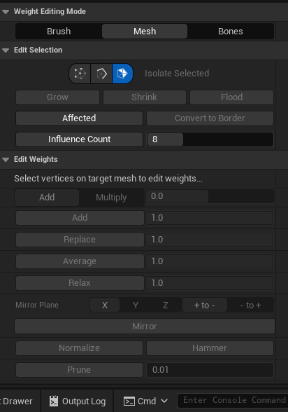
Step 6: Weight Painting Strategy

This is where working in breaks with separated meshes paid off tremendously.

My Workflow:

  1. Open Skeletal Mesh in Mesh Paint Mode
  2. Work part-by-part systematically:
    • Select a bone (e.g., joint1)
    • Paint the arm segment attached to that servo: White (value: 1.0)
    • Keep the servo housing itself: Black (value: 0.0)
  3. Real-time testing:
    • Switch between Weight Paint Mode and Animation Mode
    • Rotate the bone you just painted
    • Check for vertex deformation issues
    • Any vertices that "stretch" or "mangle" need correction
  4. Iterative refinement:
    • Paint → Test → Fix → Repeat
    • Focus on clean boundaries between rotating parts
    • Ensure no vertices are influenced by multiple bones unintentionally

Critical Insight: The real-time viewport feedback in Unreal made this process incredibly efficient compared to traditional DCCs. I could immediately see if vertices were caught in the wrong influence zone and fix them on the spot.

Weight painting setup
Weight painting process

Phase 4: Control Rig Implementation

Step 7: Create Modular Control Rig

Finally, the moment we've been working toward! This is where Unreal's Control Rig system truly shines.

The Setup:

  • Right-click your Skeletal Mesh in the Content Browser
  • Select Create → Control Rig → Modular Control Rig
  • This opens the Modular Control Rig Editor
Control Rig setup

Step 8: Add Physics Dynamics (Chain Dynamics)

Here's where we make the digital robot feel like the physical one.

Implementation:

  • In the Modular Rig Hierarchy panel:
    • Locate Chain Dynamics module in the Content Browser
    • Drag it into your rig
  • Configure the dynamics:
    • The SO-ARM 100 has a natural slight wobble after movement - that's the way the robot actually behaves in real life!
    • Adjust Damping to control how quickly oscillation settles to your liking
    • Tweak Stiffness to match the servos' holding force
    • Set Mass based on the physical arm segments
  • Test in real-time:
    • Enable Live Preview
    • Animate a joint
    • Observe the physics simulation

The Result: With just a few clicks, you have a fully rigged robot ready for animation with realistic physics behavior!

Chain dynamics
Final rig result

Phase 5: Final Polish and Creative Freedom

Step 9: Expose Controls for Animators

The beauty of Control Rig is creating an animator-friendly interface:

  • Create custom controls for:
    • Individual joint rotation
    • IK/FK switching for the end effector
    • Preset poses (home position, extended, contracted)
  • Add visual gizmos for intuitive manipulation
  • Set up constraints that match the physical robot's limitations

Step 10: Real-time Visualization

With Control Rig, you can:

  • Plan and give Animators a way to Visualize robot paths before sending to hardware
  • Direct connection with Unreal using http to drive control rig position
  • Create training animations for educational content
  • Test motion planning in virtual environments
  • Drive the rig from external data to combine robot telemetry, motion capture, etc.

The Learning Process with a Group of Riggers: Iteration as a Way of Fixing Errors

I've discovered that redoing projects in Unreal always works out in the long run. There's a profound rhythm to it:

  • Observe - Watch professionals demonstrate the workflow
  • Attempt - Try it yourself, making inevitable mistakes
  • Execute - Actually complete it, learning from errors
  • Refine - Redo it properly with deeper understanding

Each iteration revealed new layers. Control Rig isn't just about making things move—it's about building intelligent, procedural systems that respect the underlying mechanics of what you're animating.

The Hardships and Breakthroughs

Challenges I Faced:

  • Learning curve: Node-based rigging felt overwhelming initially
  • Transform hell: Fighting with offset pivots from CAD imports
  • Weight painting precision: Getting clean deformation at servo boundaries
  • Constraint chains: Debugging complex hierarchies at 2 AM

Critical Lesson - Make Copies & Backups: I had to redo the whole weight painting because I did not make a copy. Make Copies - Backups many times they can be a way to debug your own work better. I made a mistake of missing this crucial step and because of time constraints I did not clean up the mesh 100%.

Start Learning Strategy: Begin with low poly CAD model exports then move on to more complex intensive tasks. Unreal can handle a lot what you throw at it in terms of mesh count and vertices but keeping things sane is always better for the UI responsiveness.

Breakthroughs That Made It Worth It:

  • Systematic thinking: Control Rig forces you to understand transforms mathematically
  • Reusable modules: Building rig components that work across projects
  • Real-time feedback: Seeing results instantly, not after render/bake cycles
  • Unified pipeline: Rigging, animating, and rendering in one environment

Gratitude: The Team That Made This Possible

None of this would have been achievable without extraordinary support:

  • The Epic Games Team: They showed up for nearly every question, every roadblock, every "is this even possible?" moment. Their commitment to developer success is genuinely remarkable.
  • The Instructors: Who taught not just techniques, but ways of thinking about rigging problems. They shared professional workflows and industry wisdom you can only gain from years in production.
  • The Amazing TA: Patient, knowledgeable, and always willing to dig into the weirdest edge cases. Technical Artists are the unsung heroes of any pipeline.
  • Fellow Riggers: Learning alongside other professionals pursuing Control Rig mastery created a collaborative environment where we could share discoveries and push each other forward.

Special thanks to: Julie Lottering, Chase Cooper, Jeremie Passerin, Matt Ringot, Sara Schvartzman, Ferris Webby, Helge Mathee, Benoit Gaudreau, James Burton, Shenaz Baksh, Sean Spitzer, and Kevin Miller.

Why This Matters Beyond One Robot

The SO-ARM 100 project represents proof that Unreal Engine can serve as a complete content creation environment, not just a rendering engine. For projects demanding tight integration between animation, physics simulation, real-time interaction, and educational visualization, being able to rig entirely within Unreal eliminates entire categories of pipeline friction.

For my work in medical education and AR/VR training, this workflow opens incredible possibilities:

  • Rigging complex medical devices
  • Surgical robots for training simulations
  • Anatomical models with procedural controls
  • Interactive educational experiences

The Takeaway

  • CAD models into Control Rig? It geeked me out like playtime, not work.
  • Unreal's UI workflow? Delivered results that exceeded traditional DCCs.
  • From bone structure to weight maps? Streamlined and intuitive.
  • The SO-ARM 100 now moves with precision and purpose—100% rigged in Unreal Engine with Control Rig. And that feels like a victory worth celebrating.

Resources

  • Complete step-by-step guide to rigging the SO-ARM 100 educational robot using Control Rig in Unreal Engine 5
  • From CAD files (.STEP format) through FreeCAD conversion to glTF
  • Importing and positioning mesh in Unreal's Modeling Mode
  • Creating skeletal mesh with bones at servo motor locations
  • Weight painting strategy for clean deformation
  • Modular Control Rig implementation with Chain Dynamics physics
  • Real-time visualization and animator controls

Key takeaways

  • STEP files are the industry standard for CAD data exchange in robotics and engineering
  • FreeCAD is a free, open-source tool for converting CAD files to glTF format
  • Unreal Engine's Control Rig enables complete rigging workflows without external DCCs
  • Real-time feedback in Unreal makes weight painting and bone placement significantly faster than traditional pipelines
  • Chain Dynamics module adds realistic physics behavior that matches the physical robot's actual movement characteristics
  • This workflow is particularly valuable for medical education, AR/VR training, and interactive simulations
  • Iteration and backup copies are crucial—redo projects to gain deeper understanding
  • Start with low-poly models before moving to complex CAD exports for better performance

Similar videos